
There were many lessons to be learned over the past few days as we finally got Blue Skies Cabin a proper mini split heating and air conditioning unit in preparation for the coming summer months at Rally Creek. There was a lot of prior work that went into this that helped make the past few days a success; Or a partial success at least.
Before I get into the details, let me touch on some of the key lessons and tips or tricks from this latest project.
Lessons Learned Installing A Mini Split In An Off Grid Tiny Home
The Vacuum Pump
- Any mini split, including many of the DIY units you find online, will require a vacuum pump.
Luckily one of the Rally Creek partners, Brett already had one. - The vacuum pump will need a mini split adapter.
Thankfully Brett had one of these as well, yay! - You will need to make sure to tighten the connection between the vacuum hose line (the blue line) more than just “finger tight”. Snug with some channel lock of vice grip pliers is recommended. This cost use a few “trial runs” of vacuum/leak testing at an hour each (30 minute vacuum, 30 minute wait to check pressure).
- You really only need to vacuum for 15 minutes, not 30.
The Electrical Stuff
- The mini split is an AC device, running at 120v (actually 115 in our setup), so the power consumption — especially calculations base on amps need to keep that in mind. I did not, which had my potential run time calculations based on a stack of 12v 100ah batteries off by a factor of 10.
- When using “off the shelf” standard home breaker boxes, they are almost ALWAYS designed with a typical home wiring system setup for 240v (two 120v legs) coming into the top of the box with 4 wires (Red live, Black live, White neutral, Green or Bare Copper ground). A 120v inverter will only have ONE live line, meaning only one side of the break box will be powered.
- Our mini split is wired to the HEAT PUMP (outside part), and most you find will be done the same way and hard-wired. The blower (inside part) on our unit is connected through a special cable to power it and “talk to” the heat pump.
The Solar Power Lessons
- All of your power needs should be DOUBLED when doing the math.
- Solar panels have an average output of HALF or less the rated output, a 100W panel pushes maybe 50W most of the time on a sunny day. Far less on cloudy days.
- Batteries can only use HALF of their rated storage capacity.
- Inverters, controller, and general heat loss means you are losing another 10% or more in overall system losses.
Installing A Mini Split Meant Electrical Upgrades
We already had an array of solar panels, a charge controller, a couple 100Ah 12v batteries, and a 2000W inverter along with a bunch of cables and connectors to get those things wired up to each other. Those items and the setup are noted in prior articles. Now on to the upgrades we felt were prudent for trying to run a mini split 100% off grid powered by sunshine.
During the entire wiring phase our inverter is TURNED OFF. After we got the outside breaker box with the TT30 outlet installed we made sure our breakers were all OFF before plugging in the RV cable to connect to the cabin, and left it UNPLUGGED while wiring inside the cabin. When we put in our breakers we always start with them OFF. We also wear gloves to add another layer of protection while wiring.
More Power Storage With Battery Upgrades
To start this project we needed to upgrade our battery capacity. 200 amp hours (Ah) was not going to cut it, especially since gel batteries should only be depleted to 50% charge. We started by doubling that to 400 Ah by adding (2) 100 Ah Weize 12 Volt Gel batteries.

In order to optimize performance and storage you need to use the same battery type, so if you start with gel batteries use only gel batteries in the battery array. Each type of battery has slightly different charging characteristics such as how much voltage is needed to push power into the battery, called boost voltage, which varies slightly be the type of battery. This lets the charge controller do its job correctly.
You also want to use the same CAPACITY batteries as you extend the array, in our case 100 Ah 12 V batteries, because they are fairly easy to lift at about 70 lbs (32 Kg) each. Since we are not using them for motion (a golf cart or similar), weight is less of a concern, and you get more power per dollar spent than LiFePO batteries.
Two more 100Ah gel batteries it is.
These continued our parallel connection to the existing batteries, increasing the storage capacity (total amp hours) but NOT the voltage. We now essentially one large 12 volt battery with 400 Ah storage capacity. They are connected using standard M8 to M8 lug style cables, iGreely 8 AWG cables. We added two batteries and thus required two sets of these cables.
Adding An “RV Style” Power Connection
Now that we have more storage, it is time to get more power from the Renogy 2000W Inverter over to our cabin. Since the mini split can pull up to twice the rated consumption (7A in heating mode is the max, so 14A here) we need to put it on a 20A circuit. The standard 115V outlets on the back of the inverter are only rated for 15A.
That means we need to use the Live/Neutral/Ground (LNG) connector on the inverter to draw more amperage. We also don’t want our cabin hard-wired so we opted to go with an RV style connector, technically a TT30 connector which is standard on many RVs. It allows 30 amps and provides a weatherproof connection, perfect for our needs.
The RV Breaker Box and Outlet
To pull this off we decided to mount a weatherproof outlet box that includes a standard TT30 outlet. In hindsight we should have probably opted for a simple TT30 ONLY outlet. it would have been cheaper for our current needs and far easier to install, however we opted for a multi-port outlet along with breakers.
Our Connecticut Electric Breaker Box was way overkill, but this allows for future expansion without having to re-install an electric box and pull new wires. This box is setup to handle 240V power and provides the desired TT30 RV Outlet, a standard 110V GFCI outlet, and a NEMA 14-50 240V outlet in one box. It also includes breakers for everything. This added breaker is a nice safety feature should our hard-wired line try to draw too much power. For now we will only use the TT30 outlet with a 30 amp fuse to power our cabin. Sadly the 110V GFCI is wired to a different leg in the breaker box than the TT30 which means one-or-the-other with our 115V single-leg inverter.
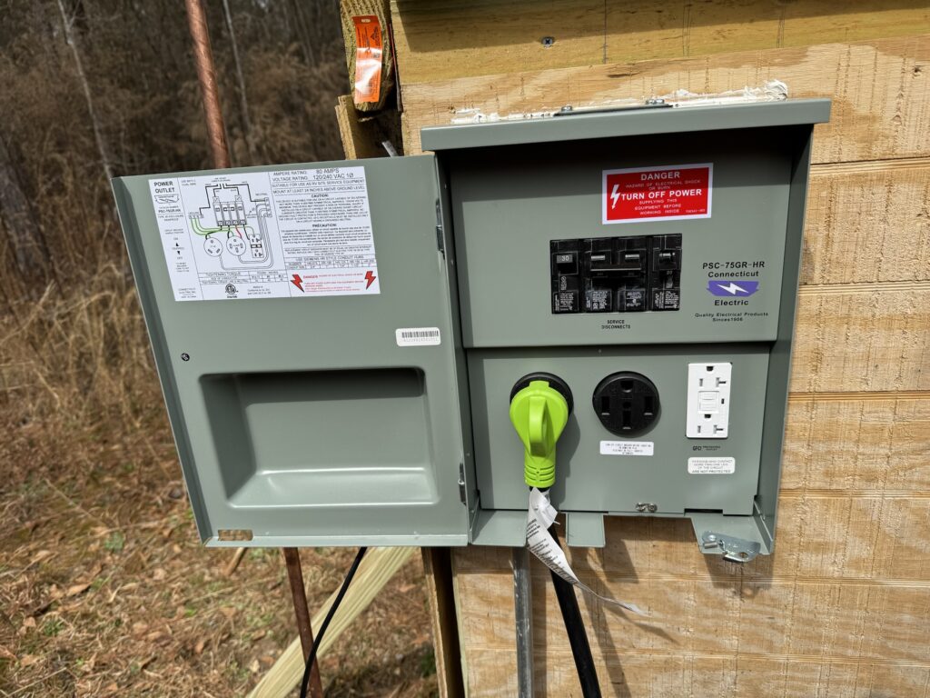
We mounted this box to the outside of our solar shed and wired it using Southwire 12/3 outdoor wiring. This wire is meant for 240V systems and includes a Red live, Black live, White neutral, and copper ground wire. It is jacketed in a protective covering that is UV protected and moisture resistant meaning it is approved for direct ground burial.
We only used the Red, White, and Copper wires on the inverter side connected the live red wire to the left side of the breaker panel to power the TT30 outlet. That leaves the NEMA 15-50 “half powered” and the 110V GFCI unpowered. We did this to provide future expansion as we hope to some day add enough power to replace the Renogy 2000W 115V inverter with a larger unit that not only provides more power but can put out 240V from the inverter. In a pinch we could potentially charge our electric vehicle at a much faster rate than the trickle provided by the 110 volt GFCI outlet, and since our EV has a NEMA 14-50 mobile adapater that helped make our decision to choose this unit. That upgrade will also mean we will have readily available 110V GFCI protected outlets right at our solar shed for running our power tools outside with a much shorter extension cable. Shorter is better for efficiency when it comes to electrical power.
Once we got that wired up, it was time to connect to the cabin.
Cabin Side Wiring To Support A Mini Split
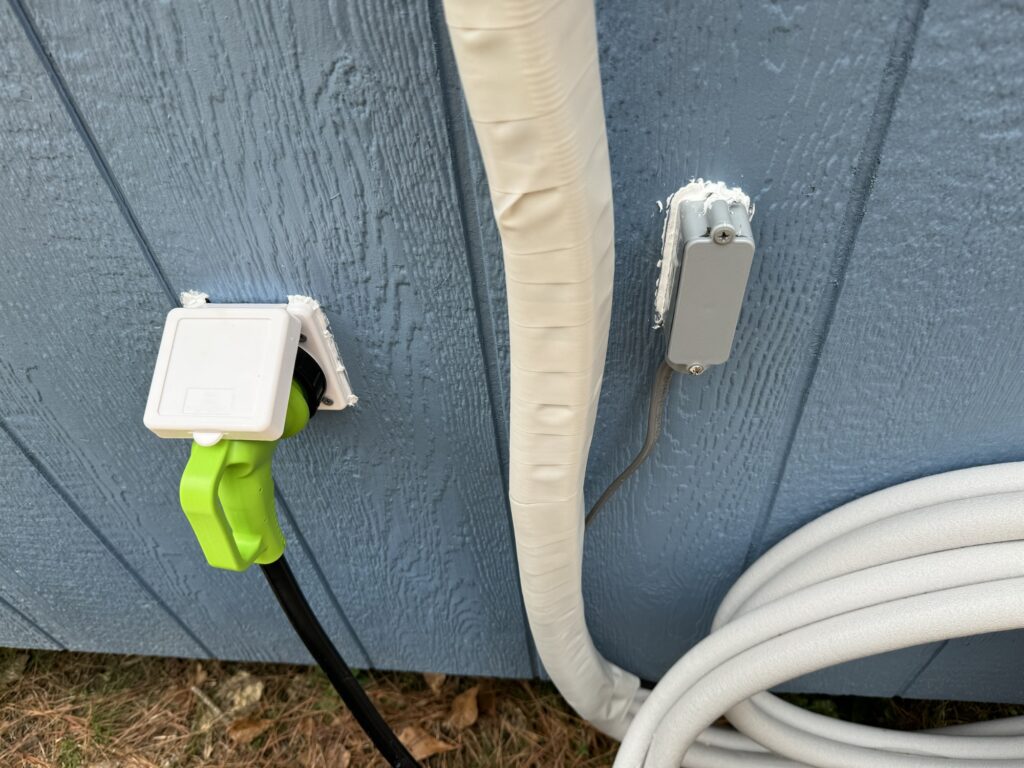
On the cabin side of things we needed to replace our exterior outlet, the PAULINN 15 Amp 125V AC Power Inlet, which was a 110V “shore line” adapter. On the outside of the cabin it provided a weatherproof inlet where you could plug in a standard outdoor extension cord. On the inside of the cabin it provided a Y-adapter with two 110V standard outlets, essentially a basic extension cord Y adapter but with a weatherproof mounting fixture around the end that goes into the extension cord.
We remove the PAULINN 125V Power Inlet from the side of the cabin and replaced it with an RVGuard 125V 30A RV Power Inlet. This allows us to connect our cabin to the inverter using a standard twist-lock 30 amp RV cable, we chose a Liesure Cords 90 degree 15′ RV Power Cord.
On the inside of the cabin the RVGuard RV Power Inlet provides 3 screw terminals to hard-wire a standard 2-wire AC cable to the port. We used Southwire 13055926 12/2 UF Wire which is standard for 110V, again with the UV and burial rating, for the few dollars it allows us to use this wire in any of our outdoor applications, and on this tiny home property there will be plenty of that in the future. We attached this inlet port to an interior breaker box that we are using to distribute power to our cabin and the minisplit.
The Breaker Box
Our RVGuard RV Power Inlet is wired directly into the input side of a GE PowerMark Plus 125 Amp 8-space Indoor Main Breaker Kit. This kit is a smaller footprint breaker panel and comes with the breakers. We also added the GE PowerMark Grounding Kit to add to the panel. This serves as the main safety and distribution point that gets our incoming power from the 30A RV port into the rest of the cabin including our minisplit. Each breaker provides is 20A, perfect match for the rating required by the mini split.
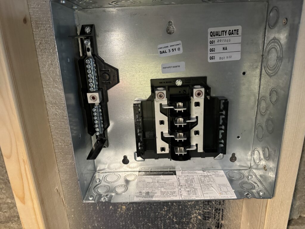
We wired the black live line to the right side input of the breaker box. As per the norm this breaker box is designed for standard incoming grid power of 240V with two live lines (120V red, 120v black) plus the typical white neutral and copper ground. Since we only have 120V (115 V technically) coming in with a single live line we only have black live, white, and neutral. Per standard we wire the black live to the right side of the breaker panel. That means only “left side powered breakers” are going to be live.
Breaker Panel Lesson : Wiring 120V Only – Use Every Other Breaker Position
Here is the thing about these circuits, EVERY OTHER breaker connection is powered by the right side black live wire. One of the lessons learned when wiring a breaker box with a single 120v phase as the main power source… use EVERY OTHER BREAKER. I originally wired the mini split to breaker position 4, then added a 110V outlet to the wall below the breaker box so we can plug in a much needed coffee maker — but I wired that into position 3 directly above the mini split connection. Guess what? That one is powered by the non-existent red live wire. Oops. Move that up a spot to position #2… problem solved.d
You can learn more about that on this ChatGPT driven article that summarizes why breaker box circuits are interwoven.
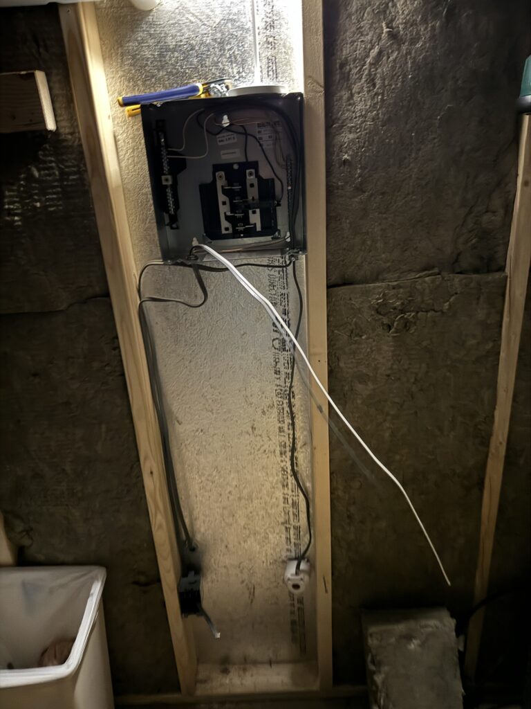
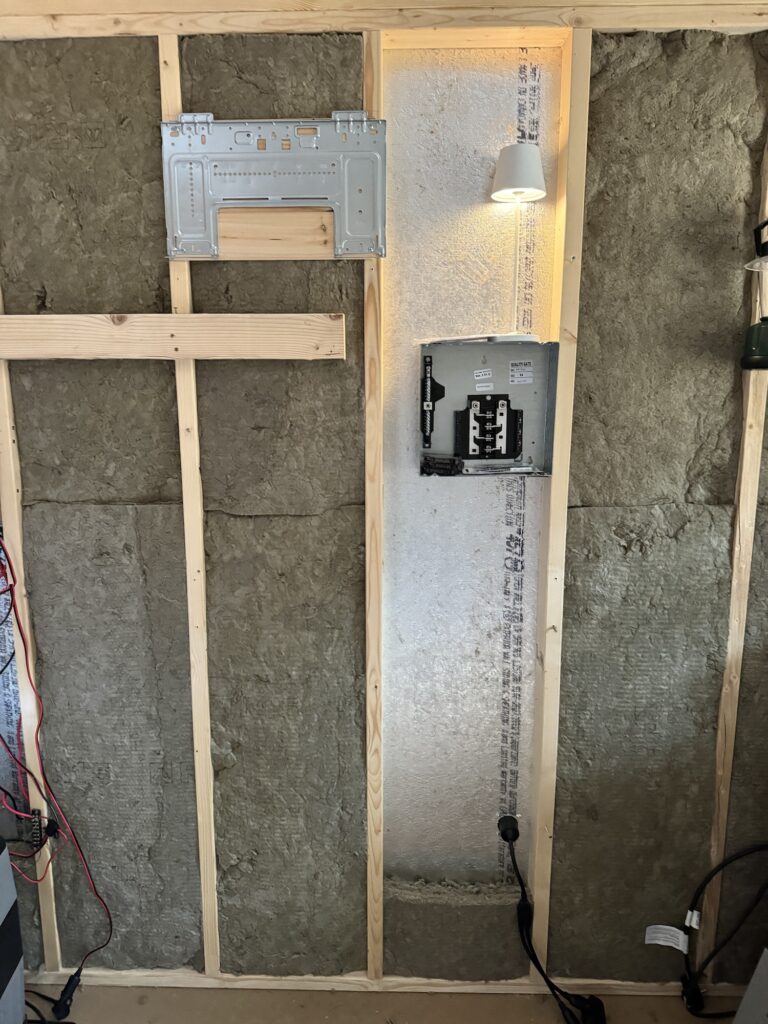
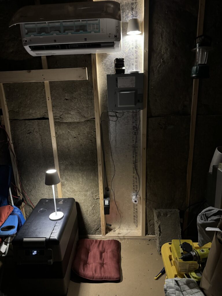
Indoor Wiring Completed
The indoor wiring for the mini split was completed, plus a bonus 110V outlet on the same wall under the breaker panel and mini split. At this point we have our RV inlet wired with 12/2 wiring to the input side of the breaker box. Black live to the top incoming right lug of the panel, the white neutral to the neutral bar that was included in the panel on the left side, and copper ground to the new grounding bar we installed on the right side of the panel.
We ran the same 12/2 wire through a 1″ hole we drilled through the wall to the outside, put in a exterior conduit adapter and secure it to the building and left enough outdoor rated cable to put our mini split heat pump out there. The mini split wiring that is now hanging outside the building is wired into the ground copper bar on the right side first, then the neutral to the same neutral bar our RV inlet is wired to, and then the black live wire to the screw terminal on the breaker itself. We then hook that breaker into the latch on the breaker panel at position 4, and be sure to snap it in securely to the live metal tab for the circuit on the other side of the breaker box. It should not be easily popped off, so be sure to check it is not loose; new breakers may take a little extra effort to snap in place the first time.
Wiring the MiniSplit – Outdoors
Now for the mini split electrical wiring. Turns out our Senville LETO 9,000 BTU mini split does NOT connect to a standard 110 outlet on the inside of the cabin near the blower as we first thought. Instead the main wiring goes into the heat pump that sits outside the building. That meant punching a hole in the side of the cabin to run the 12/2 outside rated wires to the heat pump and an unplanned trip to Home Depot to get a proper inlet port that we could use to easily route the somewhat stiffer 12/2 wire through without crimping it or stripping the sheathing, a $1 part but worth it to get a weatherproof connection into the cabin.
To make life easier, this also dictated where our indoor blower unit was placed, in a second choice location but in retrospect better location on the right side of the cabin. This put the blower near the breaker box, RV power inlet, and existing solar input/output connectors making the entire right side of the cabin the “utility ports” side. It made for shorter wire runs and an easy short run for the copper tubing for the coolant lines and control line that goes between the heat pump and blower. It also meant my wife wouldn’t sleep with one eye open worried the mini split might fall on her head, and the air conditioning would not be blowing right down onto the bed as Brett pointed out.
Once we located the blower unit inside to determine the approximate heat pump position, we could wire up the unit via the wiring panel. A screw-off panel is easily removed exposing the tabs needed to wire the 110V AC line from our breaker box. A clearly marked Live, Nuetral, and Ground point made it easy to figure out where to connect our indoor wiring.
At this point the main AC wiring is done, on to the next step – the blower and final preparation.
Installing The Indoor Mini Split Blower
Installing the blower was easy once we figure out how to open up the pre-packaged unit to access the wiring panel and the coolant lines. It was as simple as popping off two plastic panels with tabs holding them in place.
The right side was covering the ends of the coolant lines that are already insulated and “ready to go”. Just pop that off then slowly and carefully bend those lines out to a 90-degree angle. This will go through a 2″ hole we will drill in the wall of the cabin and lead outside with about a 2-foot protrusion. These will later be bent down , slowly, to a about an 88 degree angle, but not a sharp angle to basically end up with an “S-shape” tubing that runs down the back or the blower, about 90-degrees straight back (more like 92 degrees, a slight down slope, out the back of the building, then down 88 degrees toward the ground.
The left side has a pop out panel that makes it easier to see where to run the control wire that will connect to the heat pump. Pop off a small panel on the front of the unit after lifting up the main swing-up cover to expose the control wire wiring block. it has the same live, neutral, ground screw connections as the heat pump as well as 2 “data” wires that let the blower and heat pump talk to each other. Which wire goes where is clearly noted on the label on the back of the panel. Route the wires from the back to the front of the unit, screw the right colors onto the proper terminal, and close it back up.
Mounting The Blower
LOL, I know you got a good laugh out of that heading Dave… admit it.
Despite the connotations, this was a relatively easy task that was far less exciting that it may sound. There is a metal mounting plate included with the blower that is attached to the back, this was removed earlier to be able to setup the wiring and copper tubing for installation.
This mounting plate is secure to the studs in the wall (preferably) thought it does come with 4 plastic drywall anchors if your wall is already finished (ours was not, thankfully). Please do NOT use those cheap-ass plastic anchors if you are mounting this blower unit. It will vibrates as it has spinning moving parts inside and those anchors very likely will not hold in the long run. Instead please go get some metal wall anchors for $5 from the hardware store. It will be far cheaper than fixing a broken coolant lines and recharging the coolant after it all leaks out when the unit falls off the wall.
Once the bracket was set level and mounted with 6 screws to the studs, it was time to measure the place to cut the 2″ hole to go outside the cabin. Since we had the option of the exact location to run that exterior connection it was easy enough to keep the lines how we set them, straight back at the bottom right corner of the unit. The manual has measurements for offsets from the bracket for left or right back side routes. You can also run the lines out the left or right side of the blower if your installation requires that, running the coolant lines along the wall if necessary. In our case the job was easy, 4″ to the right or the bracket and 2.5″ from the bottom, drill a 2″ hole in the side of the cabin at a slight downward angle.
Place the plastic collar on the outside of the hold, and cut the provided 2″ PVC to match the thickness of the wall and attach it on the inside of the cabin to the collar.
We can now lift the blower up to the bracket, hinging it onto the top while routing the conduit lines out the new hole in the wall through the PVC and collar. pick up that power and data wire and flexible drainage tubing and put that through the collar. Ensure the drain is ON THE BOTTOM or it will not drain properly and can cause water intrusion or at least hold water for mold and other crap to grow.
Push down slightly on the blower and snap it onto the bottom of the bracket. We are good to go…time to go outside and finish the job.
Connecting Coolant Lines and Running The Vaccuum
Now that the blower it mounted and our coolant lines, draining line, and power/data line is outside we can connect the pieces. First connect the power and data lines from the blower to the heat pump. These are well labelled , follow the colors and labels on the panel of the electrical panel and double-check it all when finished. There will be a live/neutral/ground connection running inside to the blower. There will be two data lines connecting the blower and heat pump as well. Screw in the eletrical panel cover.
Remove the bottom coolant line cover. In the kit there is a copper line kit that is about 15′ long, way more than we needed for this installation. One end connects to the copper coolant lines handing out the wall from the blower. The other attaches to the heat pump. They will only fit one way as the high pressure and low pressure lines are different gauges.
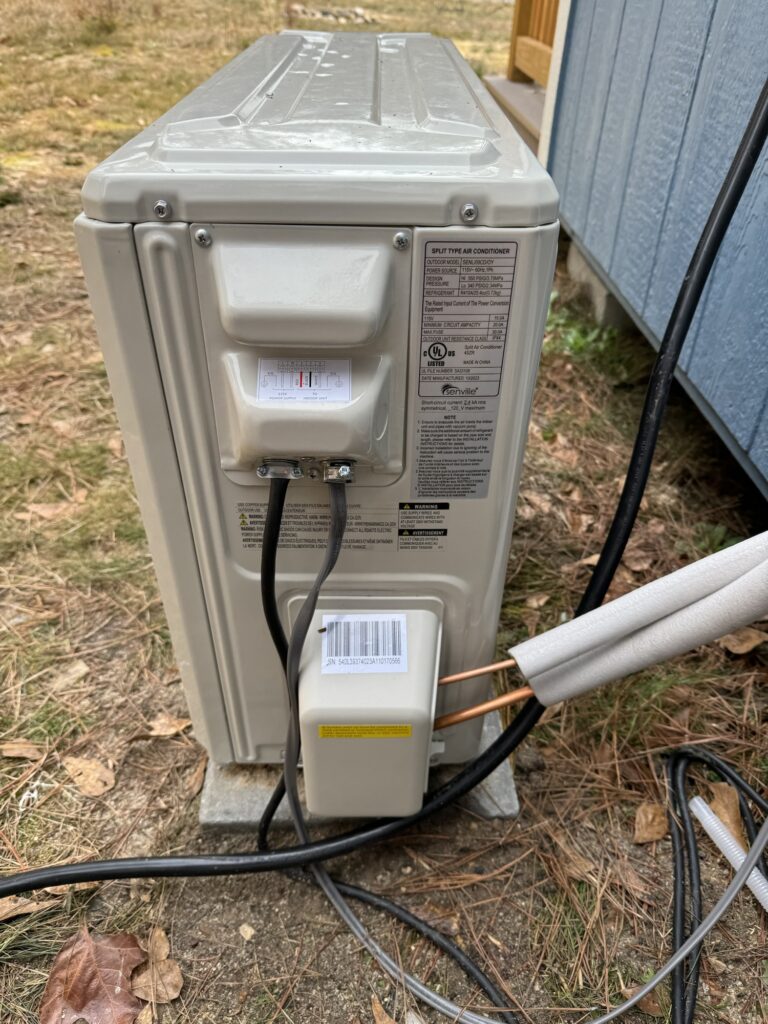
Since the coolant line connector is already flared and has a compression fitting installed from the factory, we didn’t want to mess with that. We simply left the extra 8 feet or so of coolant line in a coil with no sharp bends, very similar to how it shipped from the factory, hanging down near the heat pump. They are already wrapped in insulation so we are not too concerned about losses in efficiency, especially since this smallest 3/4 ton mini split is twice the size we need for our 12×16 insulated room.
For maximum efficiency you can cut the end of the lines, but you will need a flaring kit to re-attach the compression lines properly. I’ve done compression fittings on plumbing in the past and had to flare copper lines. It takes practice to get right. if you have imperfections it will leak. If you take on this extra step keep some extra tubing for the first few tries, if you cut to to exact length you may find you have no “wiggle room” to fix any mistakes. We opted to skip that and take a slight hit on efficiency especially given our temperate southern climate.
Now that all our lines are connected, time for the sucky part – literally.
Vacuuming The Lines
They usually don’t point this out, but all these mini split systems need the air in the extension lines and blower unit needs to be removed. This requires a vacuum pump. They also won’t tell you that you need a special adapter to connect the vacuum pump to the mini split. If you are doing this yourself, make sure you have a vacuum pump and the mini split adapter on hand. Also make sure the vacuum has oil in it (I believe most ship with this , but it is good to check). Thankfully Brett already had all the gear.
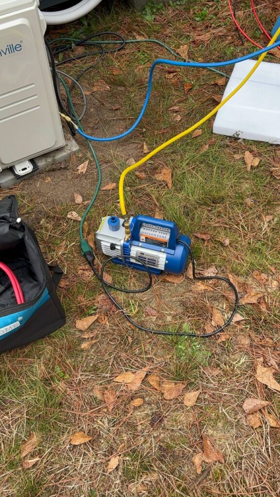
Connect the blue “low” line from the vacuum pump to the low outlet on the heat pump. This Senville unit only has one place to connect it once the lines have been attached to the unit. Unlike some of the YouTube videos we watched to refresh our memory of the process, DO NOT just finger tighten the connection. Use channel locks or vice grips to make a snug connection here or you can have a leak and need to start over. We did this process THREE times going on the advice of the first video of “finger tighten”. Several other videos say “snug but not overly tight” connection, which worked beautifully.
Connect the yellow line from the gauges to the pump. Make sure to keep the relief cap ON the unit on the input line if it has one. This was another issue we had where the first few attempts were not pulling a vacuum. It won’t pull air from the blue line, and thus the coolant lines in our system, if it can pull air more easily from the relief cap. Those “extra caps” should stay one where nothing is attached.
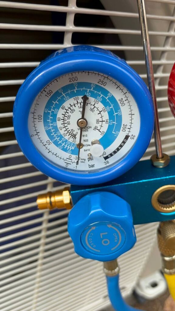
Open the low pressure blue valve on the vacuum, then turn on the pump. Let it run for 15 minutes before turning it off; Again our first video said 30 minutes when nearly all others said 15. Turns out 15 was plenty. If all is setup properly you should see the gauge on the low pressure side start moving from 0 down into negative numbers after a couple of minutes. if you do not you likely have a leak or incorrect connection somewhere. Stop and check all your connections are correct and secure.
If all goes well, the pressure gauge should read something near -30 (I’m guessing PSI)? Indicating a good vacuum. Turn off the pump leaving everything connected. Watch the needle. If it moves up , even slowly you have a leak. Come back in 15 minutes and check again. If the needle didn’t move you are good to go.
Keep in mind the leak can be anywhere — the extension lines that you used to connect the blower to the heat pump , check the blower end up near the top where they come out of the building and the lower end where it attaches to the heat pump. When making these connections you can use liquid nylon or Loctite non-permanent ONLY , you may need to replace the lines in the future. These products and help make a tighter connection and seal any small leaks at the compression joint as well as keep the parts connected over time by “lightly” securing the compression nuts in place. Also keep in mind the leak can be coming from the pump connection starting with the blue line connection to the heat pump, or the connections to the gauges. Check them all and start again. If you cannot find a source for the leak, buy a leak detector tool to help isolate the area of the leak. Keep in mind it could be compromised tubing if damaged in shipping or if you did not bend the lines slowly and keep the bends less drastic.
No leaks? Charge The System
No leaks after the 15 minute vacuum and 15 minute waiting period? Great! Quickly disconnect the blue line from the heat pump. Install the protective cap back on the vacuum connector on the heat pump to keep it clean.
Now open the larger low pressure nut on the heat pump, it is on the end of the coolant connector. Open it partway and listen for the refrigerant (my old ass still calls it Freon not R410 or whatever they use now). You should hear it moving from the compressor into the lines. Open the valve all the way and turn it back a quarter to half turn. Open the valve on the high pressure side all the way, then back a quarter-to-half turn.
You are now ready to test the system!
Did The Installation Of A Mini Split Go Well?
Time to test how we did installing a mini split in an off grid tiny home. First thing, check the electrical, turn on the inverter. Check, no blown circuit.
Plug the RV cable into the cabin, then turn on the 30A breaker in the outside breaker box. Still not sparks, the breaker didn’t trip. Sweet!
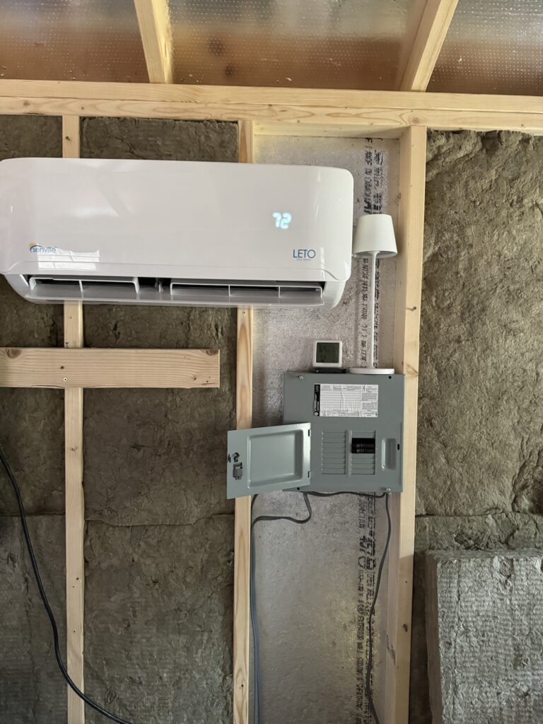
Now flip on the 20A breaker for the AC unit inside the cabin. Nice! The blower unit lights up and shows 72 – the preset temp on the unit.
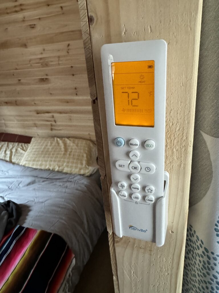
Put the batteries in the remote and press the power button. The blower moves the air louver like a droid waving at you.
Set the mode to cooling and knock it down to about 65 degrees, just below the 67 degrees in the cabin. 30 seconds later… SUCCESS! Cool air is coming out our our mini split. We have sun-powered heating and cooling at Blue Skies Cabin. This is going to be a huge upgrade.
In Review
A few things were learned along the way about using vacuum pumps, wiring breaker boxes properly, and how to get heating and cooling from the sun via solar power.
We still have some homework to do, however. Despite the insanely good, by today’s standards, efficiency of this unit the battery and solar system was not sized properly. While this 9,000 BTU unit with a SEER 21.5 rating is one of the most efficient you can buy it does draw 7A in heating mode, and 6A in cooling mode. That is very little compared to others, the next closest 3/4 ton unit needs 9 and 10 amps in comparison. Some get closer but are not highly rated, so we won’t mention those here.
However my math was wrong. I sized the system assuming 7A max draw, included the inverter efficiency of 10% losses so figured we needed 8A to heat the cabin. However that is 8A at 120V (115 actually). Our batteries are 12V. That means my calculation was off by an order of magnitude. The inverter will pull 80 amps per hour if the compressor ran a full hour, not 8 amps. Another lesson learned.
In reality our batteries are likely to be 100% full each day. With the mini split always on and set at 78 degrees it should mean it only runs 5-10 minutes at a time to get a rising 80-degree cabin back down to 78 degrees. While we need to take real world measurements, I am guessing that during the spring even in direct sun the cabin will only heat up enough to maybe run the compressor for 10 minutes every half hour at most.
I will delve into more details on “The Math of Off Grid Mini Split Cooling” in another article.
In the meantime, I would consider this project a success despite running out of charge earlier than expected on a chilly 36-degree morning and waking up to now power and a 42-degree cabin the day after the mini split was installed. The rain and constant cloud cover did not help our cause!