
This past weekend we got our first cabin, Blue Skies Cabin, fully off grid thanks to a basic solar system. Below is my notebook on what we have done. It is certain to be revised and refined as we move forward, but the initial rudimentary setup has proven the concept. Making it “legit” in 2024 with some general capacity and safety upgrades is on the punch list.
Starting Out – A Simple Solar Kit
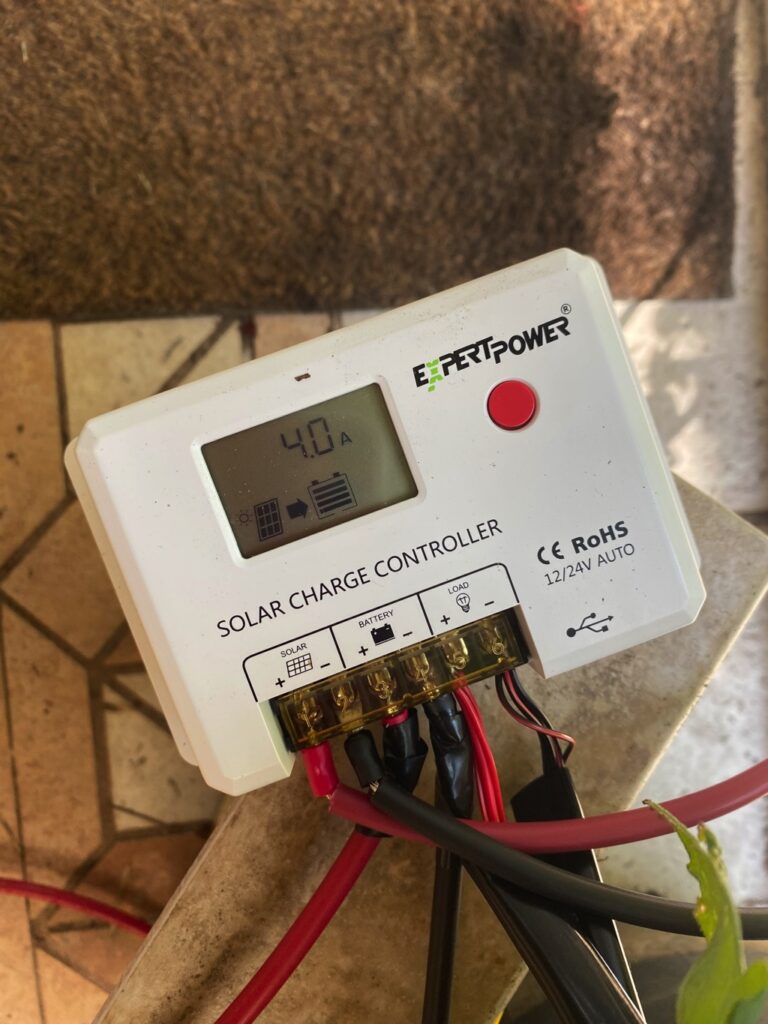
We started out with a super basic solar kit from Expert Power that we purchased on Amazon for less than $200. It had a single panel, an entry-level charge controller, a 21 Ah battery, and some cables to get it all wired together. It was the perfect starting point to learn about solar and the various pieces that make it work. Knowing literally NOTHING about solar, this was the introductory “home schooled crash course” or generating and storing power from the sun.
The goal was simple, learn a bit about how solar works and the components needed – then see if we could get the basic 12v 0.7A fan on the composting toilet running “on the sun”. It makes the indoor composting toilet virtually odor-free, which gave us some incentive to get it working.
Going solar meant saving literally $5k+ in electrical costs that would have been the “entry level ticket” to pull a 110V line over 150ft across the property. Thank you permitting fees, regulations like GFCI circuits and expensive in-ground conduit, and a bunch of other shit needed just to send 110V across the property to plugin in a simple “wall wart” to plugin in a low-volt/low-amp fan. Solar was the right choice here.
In short, the setup worked.
And yes, the panel goes outside the cabin. At first we would disconnect the load (the compost toilet fan – no, this is not a pun) an carry the battery, controller, and panel outside every time we arrived on site then bring it in after a day of charging. Eventually we wired an external port to the shed with MC4 connectors so we could leave the battery and panels outside — more on that later.
Expanding Our Power Footprint
Soon after proving the basic concept worked, it was time to upgrade as we knew we wanted to add more creature comforts. High on the list was a new cooler that we wanted to make “run on the sun”. Keeping this cool using the power of the sun seems like a neat science trick. Let’s do it!
The Solar-Powered Cooler Experiment
After some research we purchased a 12-volt cooler for the cabin. This would serve as our “weekend fridge” which meant we could stop making runs to the local grocery store or ice house to pick up ice to fill the cooler (and empty the water every day or two). The 12V cooler is designed primarily for use in an SUV for weekend camping or long road trips. It is a bit costly for a small cooler, but it does have an actual compressor which means it can cool “for realz” (some cheaper products use electric thermal cells which don’t really work worth a damn). It also can run on 12-volt.
The 12-volt “native input” — in this case using the standard “car cigarette lighter” interface, means you use more of the power for “doing work” than you would if you convert 110V AC power to DC power. Any time you convert power from DC to AC , or the other-way-around, AC to DC you lose energy. Today the best inverters (the “tool” that does the conversion of AC to DC or vice-versa) are at best 93% efficient; They lose 7% of the energy you gather “from the sun” to “the ether” (heat and electrical resistance loss mostly is my guess). Most inverters, like those wall warts everyone is used to seeing are FAR WORSE. Not long ago the average was 85% efficient, and I’m not sure it has gotten better — more efficient means more cost and we all know how that story goes.
However, even by skipping the 110V to 12V DC conversion via the power-brick that comes with the cooler (yes, we had to cheat the first time we used it and run it on the grid-based 110V power) the cigarette-lighter 12V cooler still draws about 5A whenever the compressor is running. Without the compressor, when it is just maintaining the temp it is basically off and draws < 0.07A through electric system losses.
Power Calculations
We have a 21Ah battery. Assuming the 100W panel charges if fully ever day (which it doesn’t – clouds, shade, etc. change this), we have 21Ah to start every evening when the sun goes down. On average we have 9 hours of useful charging time and 15 hours of “on battery” time — this is not perfectly accurate but makes the math a little easier.
| What | Consumption | m/h (%) | Overnight Consumption |
|---|---|---|---|
| Compost Fan | 0.07A | 60 (100%) | 0.07A * 15h * 1 = 1.05 Ah |
| Cooler – Standby | 0.07A | 40 (66%+/-) | 0.07A * 15h * .66 = 6.93 Ah |
| Cooler – Running | 5A | 20 (34%+/-) | 5A * 15h * .34 = 25.5 Ah |
| Total | 33.48 Ah |
Obviously our 100W panel and 21Ah battery is not going to keep up.
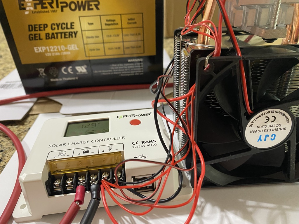
More Solar Power
By the end of the summer we now have our composting toilet on solar power and wanted to get the new cooler off-grid ASAP. To achieve this goal we did a bit of homework. It was time for some upgrades. We needed a bigger battery and another solar panel. After some research our introductory 10A pulse modulated controller would handle the load of our DC units , the power coming in from the solar panels, and be able to keep the 100Ah battery “topped off”.
What did we add to get more solar power –
- A 100Ah Renogy 12V Battery — that should allow our cabin to run for 3 days without any sun, or on those longer winter nights
- Another 100W Renogy solar panel – this can help keep things “topped off” in that new larger battery as the cabin DC load is basically off 24 of 30 days/month.
- Longer connector cables from the cabin to the solar shed for PV and batteries
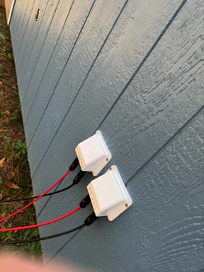
- Some outdoor MC4 connectors to get power “through the walls” while keeping them weather (and bug) resistant
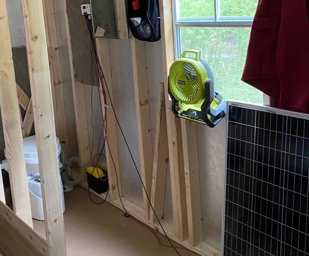
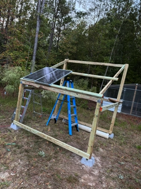
The Solar Shed
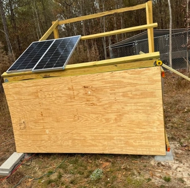
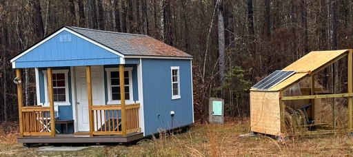
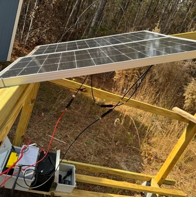
We also wanted to get the larger battery out of the cabin and get setup for an expanding solar system. That meant it was time to build a rudimentary “solar shed” to attach panels. We decided to build a basic solar stand or “shed” for many reasons. One reason was that we want our cabin to remain somewhat mobile, in case we ever decide to relocate our “tiny home style cabin” to a new location some day. We also want to be able to easily break down and rebuild our solar stand as we learn more about what will work and what will not. We slapped together a basic frame and threw the panels on there to keep them off the ground and, more importantly, not permanently attached to our cabin. Our cabin now has external MC4 DC connectors for solar in as well as battery I/O and a 110V “shore line” input receptacle in case we ever need to go back “on grid” — hopefully not after our most recent upgrades.
Phase 2 Results
At the end of Phase 2 we had a new solar shed started, 200W of solar panels pushing power into a 100Ah battery. Our entry-level 10A charge controller might be inefficient but it can keep up with managing the charge from the PV array to the battery. It also provided a USB port to charge some of our devices as well as the 12V output where we had our compost toilet wired. We tested the cooler on this setup temporarily , which worked, but we did not have time to connect the 12V bus to the load output of the controller to run two separate 12V devices (toilet fan + cooler). While I’m all for temporary “redneck hacks” to get shit working, I didn’t want to put this together with “wire nuts and duct tape” to get everything online. For now, the cooler stayed offline but we could swap it out if/when needed.
We can now run our cooler and our composting fan whenever we need it. Nice!
Off Grid Upgrades With 110
To close out 2024 we made a final push to truly set ourselves up for 100% off-grid living at Blue Skies Cabin at Rally Creek. To do this we know we are going to need good ol’ fashioned “American Power” — that 110 volt “smiley face” outlet we all know and love with the full 15 or 20 amps of output to power our “off the shelf” (and far less costly) devices. Our ultimate goal here is not really to just “plug things in willy-nilly” whenever we want but to get some much-needed items hooked up on-site and off grid.
Top of the list is getting our 110V power-hungry rainwater pump off grid. It pulls too much power for the second phase setup , and even our latest upgrade from this past weekend. Part of this is not just to get the entire site “off grid” but also because the wiring we inherited for the 1100V outlets from our past owners is “totally fucked” to put it bluntly. It is not grounded, for one, which means the auto-off controller on the rainwater pump does not work properly.
Also on the list is to wire up a small 110V heat-pump to the cabin for basic cooling (much needed in summer at Rally Creek) and heat (marginal need in winter). There are a lot of new options for small spaces, like the 12×16 space at Blues Skies Cabin, that draw minimal power and are super efficient.
And last on the list , more of a “want than need”, is the keep the Starlink system plugged in and powered-up year-round mostly for security systems, but also because cell service is either great or non-existent on property. While we can monitor the site video feeds with cellular as needed, having real-time high speed feeds of that and our power and water systems would be a huge bonus.
The End of 2023 110V Off Grid Upgrade
For the end of 2023 we opted to get a basic system in place for year-end that will be our starting point for 110V power. After doing some research we landed on the following components to add to our ever-expanding off-grid solar setup:
- A second 12V 100Ah battery – wired in parallel keeping our system 12V with 200Ah total storage
- Two more 100W panels – they are super low cost at the moment, down to $60/100W panel delivered
- An upgraded PPT 40A Charge controller – more efficient, better battery controls, and able to handle a much larger solar array
- M8 to M8 cable kit to wire the batteries in parallel
- A longer MC4 cable pair for the panels and batteries (20′)
- And MC4 connector tool – make disconnecting MC4 way easier AND makes it easy to build/repair MC4 connectors
Getting this wired up and online was easier than expected. After disconnecting the solar array and batteries it was time to get started.
Solar Shed Update
First thing was to add a rudimentary “roof” to the solar shed- not the final iteration but something to keep rain out of the inverter and battery bank. Throwing on some exterior paneling on the front (south) and west side would keep out most of the weather. Eventually we will get back and enclose the entire thing and add a proper door and window on the back of the shed — but that is for another day. This is basically a place to attach the panels while keeping them off the ground and out of the way of the weedwhacker while giving us a place to keep batteries and inverters dry; And heaven-forbid if something “goes poof” and tries to burn shit down, keep it away from the cabin and the woods as much as possible.
Once we updated the shed it was time to go to work on the electrical system.
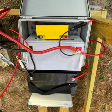
Battery Updates
First thing was to wire the 12V 100Ah battery to the existing battery in parallel – red to red, black to black. Easy-peasy. On the original battery we disconnected the run to the cabin and added in our new super-heavy-duty 0-guage 3ft wiring for our inverter. We added an upgraded MC4 to MC4 wire to connect the battery to the cabin.
The final result : new battery with a single heavy gauge M8 to M8 wire connecting negative-to-negative (first), then positive-to-positive on the original battery. Before we “ratcheted down” the M8 bolts on the original battery we added all 3 connections to negative (first) then positive connections: second battery in array + inverter cables + M4 cables to the cabin (charge controller).
Solar Updates
Once the battery was ready it was time to expand our solar array. Sadly, just 90 seconds before the UPS truck rolled in with tow more 100W 12V solar panels, one of the two existing panels fell over while measuring the layout and ripped out the M4 connector. Sad, but not the end of the world — it is an easy fix we will get to next trip (it started raining heavily the next morning, so we cut this trip short). So now instead of wiring up 4 panels in series we ended up with 3.
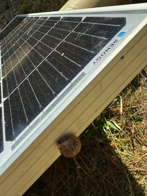
After getting the mounting screws in place (we will use a proper mounting bracket and/or rack later as we expand) it was time to wire these panels in series. The idea is to push more voltage up to what the controller can handle. Supposedly our new charge controller can handle to to 48V input at high wattage, but they are not clear if that is per the 12V/panel rating or the open circuit rating (more homework needs to be done). So maybe this is a blessing in disguise so we con’t blow up our new charge controller.
At the end of the day we ended up with (3) 100W panels wire in series — positive to the cabin input on panel #1 with negative on panel 1 => positive on panel 2, negative on panel 2 => positive on panel 3, negative on panel 3 to the input to the cabin (charge controller). The idea is that we end up with 36V of output with 300W of panels. The charge controller will “do the math” and figure out how to change the to the 12V (closer to 14V actually) to push electrons into the new 200Ah battery bank.
Keep in mind NONE of this is connected to anything yet, all wires are not plugged into the controller yet so we have a separate battery and PV array and controller.
And when we first connect our inverter and controller (below) we only had our original two panels (before I ripped the Mc4 connector out of one) to start with.
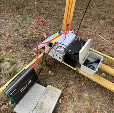
The Inverter Providing 110
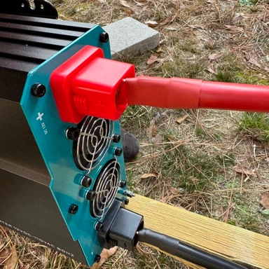
Now the “magic sauce” is the inverter. This will be our 110 volt workhorse in the future. We went with a mid-range inverter, a 2000W Renogy Pure Sine Wave inverter. Having an background in computers, I know that pure sine wave is important for sensitive electronics. Since we may add that Starlink to the mix someday having pure sine wave is important (and yes, we will isolate the circuit from the one the pump motor is on to eliminate feedback — we will deal with that later). Also many electronics, even pumps, tend to be happier with pure vs. modified sine waves — especially with a pump using an intelligent flow controller like our rainwater pump we have on-site.
The inverter is fairly simple — connect the DC input side to the 12V battery bank using those “dummy thick” 3ft M8 to M8 cables. Just be careful and don’t electrocute yourself. Gloves, goggles, and negative first, then positive connections from the batter to the inverter. Add the caps back and you’re good to go.
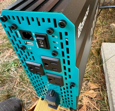
The invert is just sitting there turned off. Not consuming power, waiting for the switch to be turned on. The (3) 110V 15A (or was it 20A) outlets are ready to serve. For our needs we run a thick outdoor extension cord, about 20 feet long, from one outlet to the already-installed cabin 110V male waterproof receptacle. The pair of 110V outlets inside are ready for use to power that Starlink or anything else we may need in the cabin. All we need to do is turn on the power switch at the inverter.
We are now ready to go, but if we turn this on our 200Ah of batteries will drain fairly quickly with no input. However, we can test this to ensure it is all working, whenever we are ready. But before that let’s get our new charge controller online and let solar fill the batteries before our inverter draws them down.
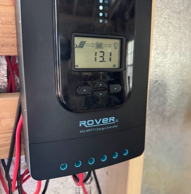
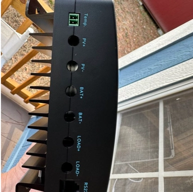
The 40 Amp Controller
Our new 40 Amp MPPT charge controller is bigger than expected. About the size of a small toaster with 4 simple buttons on the front and 6 direct wire connectors on the bottom. Wiring up this Renogy charge controller is a breeze thanks to high quality direct wire “clamp style” connectors – loosen the screw enough to push in the wire from the exterior connectors on the cabin, then tighten them. Battery input negative first, then battery positive. Wire the negative solar array input lead from the exterior cabin connector, then the positive. Super simple.
Remember, nothing is plugged in yet, all the cables are lying on the ground outside. So time to follow the controller instructions, connect the battery first – negative then positive leads. This is super easy, go outside, and these super-simple MC4 connectors mean just “plugging the pieces together” — battery connected. Step 1 is done!
The controller immediately powers up. Configure the controller via a few key presses to set to to the GEL battery type (love the simple icons to indicate which type of battery), then make sure it is set at 12V (it is, that is the default). Done. We are now ready to add the solar array.
Go back outside, jam that little MC4 negative lead into the side of the cabin input, then the positive. Go back in and check the controller.
Everything looks great! Sweet. Immediately the system is showing batteries are well over 98% meaning the new battery was likely nearly fully charged on our on-site battery was full at 100Ah after weeks of solar being pushed into it with no load. Our PV array is running between 1A and 2A depending on cloud cover – expected since it is super cloudy today.
This charge controller has a lot of useful technical info you can pull up by cycling through the menus. The PV array is pushing some amps which vary (as expected), the battery is inching up now 99% full in just 10 minutes, there is no load (we have not connected a direct DC load to the charge controller yet)… GEL battery, 12V looks normal, operating at 15C temperature, but oddly our solar array is pushing just over 40V with two 100W panels.
This last bit is odd to me. I thought the panels were 12V – and yes the “open voltage” is different, but I expected to see 24V coming in with 2 panels not 40V. Clearly I need to do more homework. The amperage looks right at 1-2A; On a good day I was seeing 2-3A from the single 100W panel (never saw anything close to the rated 5A, most I ever saw was 4A for about a millisecond one day in full summer sun) so 2A from (2) 100W panels on a mostly cloudy day seems reasonable.
All side, the controller can handle itself. The manual says it can take up to 100VDC (if I recall while writing this) before shit goes sideways.
Soon after all this was wired the new panels came in, so things were disconnected and 3 panels put in (one wire broke – my own dumb ass fault) then re-connected. Now we are getting 55V and 2A or so , maybe a bit more, fairly regularly from our (3) 100W panels — but it is more cloudy than before so this still makes sense.
AC and DC Testing – We Are Off Grid
Now everything is wired up. We have 300W of solar panels, our 40A controller, our 200Ah battery array, and our 2000W inverter. Everything is wired to the cabin. Time for some testing.
First up – power on the inverter and test the cooler on 110V via the “brick”. It works great. Draws more power this way and the battery bank drops in percent of storage a tiny bit each time the compressor kicks in, exactly as expected. Sweet.
The DC wiring is going to wait until morning as it was getting late, so for now just 110V testing.
Everything looks great, but the real test is at night. Later that night when the temps drop into the mid-40s (F) the cabin was a bit “cooler than we like”. The campfire was nice, but for sleeping mid-40s is a bit cool if we don’t want to use our sub-zero sleeping bags. This is a cabin, not a camping trail or tent after all. I brought up a small space heater we had in our garage at our house. It is old and janky and not super efficient, but it runs on 110V and draws was less than 15A (I didn’t get the rating, but if I recall that old 2005 heater was super inefficient around 10A). We plug in the space heater and it starts warming up the space. We only ran it about an hour as a test — it added a few degrees of warmth to our mostly-uninsulated cabin (we are still working on that) but it did draw down the batteries fairly quickly.
Eating Up Power
By the time the cold weather came in that evening our battery was down to about 75% (mostly from playing with stuff testing it out), but the space heater quickly pulled that down to near 60% in just about an hour. We’ll call it 15% draw per hour on our 200Ah battery array. Remember we now have a space heater and the cooler online PLUS the 7% loss converting AC to DC that even this higher-end inverter adds to the equation.
So on a 200Ah battery we went from 75% capacity (150AH) to 60% capacity (120AH) in about an hour — so we “ate up” about 30A of power in a single hour. That means our battery bank would last only 6 hours, not even the entire night. Damn.
I know the cooler was pulling 5A on DC power from earlier testing. With the wall adapter efficiency likely around 85% + the inverters itself running at 93% efficiency we can guesstimate this at 5A * 1.15 * 1.07 or about 6.2A whenever the compressor was running. The heater, running at 10A pretty much non-stop ends up being closer to 11A since the 10A rating likely already includes the “run time” and thus accounts for the internal AC/DC inverter (a wall wart built inside the box, like most devices in our homes). So the cooler + space heater are damn near 17A.
Where did the other 13A come from? From what I can tell some kind of controller math when under load. It appears the controller does not account for the inverter load very well when calculating % battery remaining.
As soon as I turned off the space heater and the cooler compressor was off, the battery % remaining jumped back up by more than 5%. That is 10A of that missing 13A right there. For now, more to learn about this setup.
Final Step – AC and DC Power
The next morning it was time to wire up a new DC wiring block. It is a cheap on rated at 10A and we are going to need something better quality, preferably with breakers and switches, but this is what I had on-hand and does the trick. Wire up the block so it can power the female cigarette lighter receptacle we can plugin our cooler into (it also has a cigarette lighter input = no AC-to-DC conversion like the wall wart and is far more efficient) a well as our composting fan. Connect this wiring block to the charge controller, negative line to the negative load terminal, positive line to the positive terminal. Turn on the DC power via the controller load on/off button — composting fan is on, fridge is on — Sweet. Full solar power for the cooler and the fan. And the math looks right… our cooler with the compressor on pulls 4.2 to 4.4 amps alone and with the compost fan we are just under 5A pretty steady. When the compressor kicks off (it is cold out so this happens in less than 5 minutes and stays off for 30 minutes) the entire DC load is < 1A.
We Did it!
Not a perfect off-grid solution by any means, but we did end up running the entire next morning 100% off-grid. We have AC power if we needed it. Our cooler and fan were running 100% on DC power from the solar array. Best of all both those units had no “conversion tax”.
Our battery was at 58% the next morning and started “filling back up” with just 3 solar panels at work on a very cloudy and partly rainy morning. Even in full rain mid-day the panels were able to find some electrons to throw into the batteries.
Next Up
We have a lot of learning to do and some additions to make.
First to figure out what the voltage difference is on what the solar array is pushing to the charge controller before adding our 4th panel back.
We want to add some additional 100AH batteries , this will allow us to run that 100Vdirect-connection line to the pump. We may need to upgrade the inverter, but I think it handles GFCI no problem.
Since the pump will drain the batteries quickly when running (thankfully only to recharge a pressure tank when the water is being used), we will want to add more solar panels to top off those extra batteries. Thankfully adding batteries and panels is super easy now, we just need to be careful about our voltage and total watts to keep within specs of the controller.
With this 40A controller and 2000W inverter we should be able to get a long ways before we need to upgrade those components; they get super costly as you move up from “tiny home size” to “full rally creek dual cabin size” to “oh, let’s charge our EVs too” size… that is for later.
Products
| Mfg / Model | Description | Details | Country | Purchase |
|---|---|---|---|---|
| Gen/Ctrl/Store Kit | ||||
| Expert Power 100W Kit | Start kit for phase 1, panel , controller, cables, and battery | 12V 100W Monocrystalline Panel 10A PWM Controller 12V 21Ah AGM : 252 W |
$180 on Amazon | |
| Generation | ||||
| Renogy 100W Panel | Solar Panel, phase 2 +100W => 200W | 12V 100W Monocrystalline | Thailand | $85 on Amazon |
| Renogy 100w Panel Pair | Solar Panels, phase 3 +200W => 400W | (2) 12V 100W Monocrystalline | Thailand | $150 on Amazon |
| Charge Control | ||||
| Renogy RNG-CTRL-RVR40 | Charge controller, phase 3 upgrade | 40A MPPT 12/24V Battery Charging 12V to 520W, 24V to 1040W |
China | $160 on Amazon |
| Storage | ||||
| Renogy RNG-BATT-AGM12-100 | Battery, phase 2 battery | 12V 100Ah AGM : 1.2 kW 5F/-15C – 122F/50C |
China | $190 on Amazon |
| Weize LP12-100-W | Battery, phase 3 battery +100Ah => 200Ah | 12V 100Ah AGM : 1.2 kW | $156 on Amazon | |
| iGreely IG-BCS0X0 | M8 to M8 Battery Cable, parallel battery expansion | 8 AWG , 2ft | $9 on Amazon | |
| Electop B08GKDKZBV | M8 to M4 Connector, attach M4 to battery bank | 10AWG, 0.82ft / 0.25m, Up to 600V, Red/Black | $10 on Amazon | |
| Wiring | ||||
| Renogy Connector Tool | M4 Connector Tool | China | $7 on Amazon | |
| Renogy | M4 20ft Cable | 10 AWG, 20ft, Red/Black | $32 on Amazon | |
| Beidelt | M4 15ft Cable | 10 AWG, 15ft, Up to 1.8KV, Red/Black, | $30 on Amazon | |
| Slocable | M4 Entry Gland | 10 AWG, 10ft | $36 on Amazon | |
| Vemote | M4 Y Branch, connect panels in parallel (up Amps, keep volts the same) | 40A, 1KV, 0.98ft / 30cm | $13 on Amazon | |
| DC Power | ||||
| Sparking | M8 DC to 12V Female Cigarette Lighter | 16 AWG, 13ft, 15A Fuse | $15 on Amazon | |
| AC Power | ||||
| Renogy RNG-INVT-2000-12V-P2 | Inverter | 12V => 2000W 120V AC | China | $259 on Amazon |
| Devices | ||||
| Alpicool CF44 | Portable Freezer | 12V/24VCD or 100-240VAC => 12V, -4F to 68F, 12V 60W when running compressor | $259 on Amazon | |
| Nature’s Head | Composting Toilet | 12V Fan , 0.07A | $1030 on Amazon |